Mô tả

Learning a basic board design is essential for everyone who would like to work in electronics or who would like to design electronic boards or products. Learning board design in the right software can open you door into many companies, help you to get a well paid job and can be used to design very complex and advanced boards.

Design a Real Board and Learn Essentials of Using Altium Designer

- Draw your own schematic
- Route your PCB and do layout
- Generate documentation needed to manufacture your PCB

Altium Designer is a Powerful Software

During this course you will learn how to use Altium Designer software. Altium Designer is a professional software used to design all kind of boards, from very simple ones to motherboards or servers. It is one of the most used software for electronic design. Learning Altium is useful for everyone planning or already working in electronics.

Contents and Overview

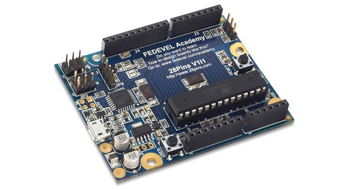
You will start with Arduino Uno reference schematic. You will learn how to re-draw the schematic, modify it, you will learn how to improve it and how to do PCB layout. The course videos are step-by-step and even if you are new in electronics or you have never used Altium Designer before, by repeating these steps, you will design your own board. By the end of this course, you will create all the necessary documents needed to manufacture the board. 

Within 15 hours you will learn how to:

- Draw schematic, including tips for component selection and important circuits
- Create components, draw schematic symbols and footprints
- Place components into your PCB
- Route PCB and useful tips about layout
- Create 3D model of your board
- Create board variants with different components fitted / not fitted
- Create Bill of Material (BOM)
- Create assembly drawings showing position of components on the board
- Generate Gerbers, Pick and Place, Drill file and other files needed for manufacturing
- Prepare professional documents needed to manufacture your PCB and assemble your board
- Bring your board to life, flash firmware and run a simple LED Blinky example

For everyone interested, the manufacturing documents created during this course can be used to build your board. Simply use PCB manufacturing data to get your PCB, buy components from Digikey and solder them by yourself.

Enjoy this course :)

Bạn sẽ học được gì

After this course, you will design your own Arduino like board.

Yêu cầu

  • You will need Altium Designer software. If you are a college / university student, ask Altium for a student license. In many countries the student license is free.

Nội dung khoá học

7 sections

Drawing Schematic and Creating Libraries

79 lectures
Introduction
00:55
What you will learn during this course
02:10
Download Arduino schematic and start a new project
02:38
Prepare to create ATMEGA328P component
06:29
Create ATMEGA328P - Schematic symbol
09:04
Create ATMEGA328P - Footprint
13:16
Prepare to create ATMEGA16U2 component
02:11
Create ATMEGA16U2 - Schematic symbol
09:35
Create ATMEGA16U2 - Footprint
17:49
How to update an existing component
01:46
Create 10 pin female header
14:25
Create 8 pin female header
06:19
Create 6 pin female header
05:27
Connect 10, 8, 6 pin headers
02:49
Create 100nF capacitor
18:29
About connecting power pins of microcontroller
01:54
Create 10uF capacitor
07:50
Create Ferrite Bead
03:59
Draw power connections
03:25
Create 1M resistor
11:18
Create 16MHz Crystal
14:27
Create 18pF capacitor
01:57
Draw crystal circuit
01:37
Connect power header
05:51
Draw crystal connection and power for 16U2
04:01
Create ICSP header
17:37
Connect ICSP header
04:00
Placing net names
04:10
Using schematic filter and schematic inspector
02:42
Connecting rest of the IO connector signals
03:47
Create 22 Ohm resistor
02:21
About connecting CLOCK, RX and TX
02:41
Create 1k Ohm resistor
01:51
Connect UART signals
02:13
Connecting ICSP1 header
03:46
Creating 2x2 male header
08:36
Connect 16U2 IO header
01:54
About RESET circuit
04:17
Creating BUTTON
12:09
Create 10k resistor
02:31
Creating DIODE
14:19
Create AND gate
12:21
Connecting RESET circuit
06:17
Draw rest of RESET connections
02:28
Creating 1x3 male header
09:35
Connecting JP1 jumper and 16U2 RESET circuit
06:15
Create 1x4 male header
06:33
Connecting JP3 jumper
01:46
Create Orange LED
12:54
Calculating LED resistor
03:26
Create 560 Ohm resistor
01:46
Connecting LEDs to indicate communication
01:15
Create and connect Green Power LED
03:12
Connecting User LED
04:15
Create +3.3V LDO regulator
14:03
Connect +3.3V LDO regulator
02:05
About power selection circuit
01:05
Create 0R resistor
01:45
Draw power selection circuit, about unfitted components
04:29
Name some 16U2 nets and about pull up resistors
02:36
Create 100k resistor
01:40
Connecting 16U2 signals, GND pins, about UCAP
02:41
Create 1uF capacitor
01:50
Draw UCAP connection and name power & crystal nets
03:06
About USB connector + Creating USB connector schematic symbol
09:34
Creating USB connector footprint
18:28
Connecting USB - Part 1
02:40
Create Varistor
09:31
Connecting USB - Part 2
02:00
Creating 100uF capacitor
11:33
Create 2.2uH inductor
09:56
Connecting USB - Part 3
02:14
Add and connect User Button
03:07
Create and connect PADs
04:56
Create and add fiducials
06:22
Create and add mounting holes
09:42
Create and add DIP socket
06:10
Create and add LINK (jumper)
04:04
About PCB and Firmware component
00:50

Finishing Schematic

6 lectures
Annotating, checking and browsing schematics
06:59
Adding notes into schematic
03:06
Finishing schematic: About Pages, Title Block and Parameters
07:36
About components and BOM (Bill of Material)
06:53
Update Altium Designer settings
01:36
Importing Schematic into PCB
04:52

PCB Placement

12 lectures
Change board shape, place mounting holes and main connectors
08:52
How to start placement, place 328P MCU and DIP socket
05:16
Change Altium settings, hide designators, setup grid, lock down components
06:05
About placement
07:18
Placement around 328P MCU
03:07
Placement around 16U2 MCU
04:36
Place components around USB connector
04:17
Placing headers, jumpers and LDO regulator
06:41
Placing buttons, 16U2 reset, LEDs
11:15
Placing remaining components
08:13
3D view of finished placement
00:46
About paper model
10:22

PCB Layout

20 lectures
Preparing for layout
19:31
Routing long connections
19:01
Routing short connections
12:07
Routing power nets
13:31
Routing ground net
11:26
Checking if everything is connected
03:18
Current status and about layout procedure for more complex boards
02:39
Importing schematic changes into PCB
04:10
Drawing power planes (polygons)
17:40
Drawing ground planes
04:41
More polygons, improving power tracks and power planes
16:25
Improving layout Part 1
13:09
Improving layout Part 2
07:20
Improving layout Part 3
15:40
Improving silkscreen layer
12:33
Adding gold company logo
03:20
Adding assembly drawing layer
11:35
Creating mechanical drawing layer
08:00
Adding manufacturing notes layer
04:41
Finishing PCB
09:33

Manufacturing documentation

14 lectures
Create board variants
09:58
Start procedure of releasing your board documentation
04:41
Generate and check gerber files
06:32
Generating NC drill outputs and drawings
04:33
About stackup document
00:45
Generate mechanical drawing
03:09
Generate assembly drawing
04:51
Generate top view drawing
05:21
Generate BOMs
14:24
Generate pick and place file
02:24
About stencils
00:48
Generate 3D PDF and STEP file
07:36
Generate PDF schematic
06:02
Back up the project and what next ...
02:55

Bringing your board to life

5 lectures
How to start with software development
03:28
Programming 16U2 MCU
06:02
Programming 328P MCU
03:08
Reprogram 16U2 MCU
01:28
Testing your board
02:02

Thank you

1 lectures
Thank you very much for signing up for this course
00:47

Đánh giá của học viên

Chưa có đánh giá
Course Rating
5
0%
4
0%
3
0%
2
0%
1
0%

Bình luận khách hàng

Viết Bình Luận

Bạn đánh giá khoá học này thế nào?

image

Đăng ký get khoá học Udemy - Unica - Gitiho giá chỉ 50k!

Get khoá học giá rẻ ngay trước khi bị fix.